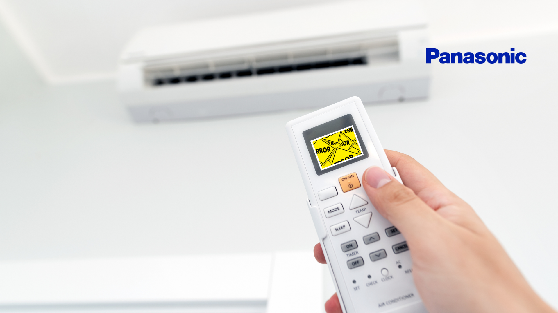

Toshiba air conditioners have built-in self-diagnosis. When the unit detects a fault whether in sensors, communication, fans, compressor, pressure, or PCB—it will show an error or “check” code. These codes help in diagnosing issues quickly, so the correct component can be inspected or replaced.
How to Read Toshiba Error / Check Codes
- Use the remote control and press the “CHECK” button (or equivalent) to enter service or diagnostic mode. All indicators (LEDs) on the indoor unit often flash rapidly when a fault is detected.
- The display shows a two-digit alphanumeric code (e.g., E01, F10, L08, P01) which corresponds to a particular fault.
- Some errors persist in memory even after power-off; they often need to be cleared manually (e.g. via a CLR button or sending a certain code “7F”) once the issue has been fixed.
Full List of Known Toshiba AC Error / Check Codes & Their Meanings
Below is a collected set of Toshiba codes from multiple sources (Toshiba manuals and authorised resellers). Some codes apply only to certain models (split, multi-split, inverter, group/central control). Use your specific manual for exact mapping.
| Code | What It Means |
|---|---|
| C05 | Central control sending error (TCC-Link central control device) |
| C06 | Central control receive error in TCC-Link central control device |
| C12 | Batch alarm for general purpose equipment interface |
| E01 | Communication failure between remote controller and indoor unit |
| E02 | Local controller failure – cannot send commands properly |
| E03 | Master indoor unit receives no data on line A-B (communication) |
| E04 | Communication error between indoor and outdoor unit (or outdoor side remote communication issue) |
| E06 | Decrease in the number of indoor units (e.g. group control; missing indoor units) |
| E07 | Communication error between indoor and outdoor units (alternate phrasing) |
| E08 | Duplicated indoor unit address (address conflict) |
| E09 | Multiple local controllers connected in a group, both configured as masters (conflict) |
| E10 | Indoor unit PSB (power supply board or a protection stage) failure |
| E12 | Automatic address start error (issue in setting up addresses) |
| E16 | Maximum number of connected indoor units exceeded |
| E18 | Communication failure between master indoor unit and slave indoor units |
| E19 | Number of connected outdoor units error |
| E20 | Other line connected during automatic addressing; mis-wiring in address setup |
| E23 | Sending error between outdoor units (communication) |
| E25 | Duplicated follower outdoor address setup (two outdoor units assigned the same address) |
Sensor / Hardware & Motor / PCB related codes:
| Code | What It Means |
|---|---|
| F01 | Indoor unit TCJ (Liquid line) sensor error (open or closed / resistance-type fault) |
| F02 | Indoor unit TC2 (vapour line) sensor error (open or short circuit) |
| F04 | Outdoor unit TD (Discharge) temperature sensor error (open/short) |
| F06 | Outdoor coil sensor (TE) error (coil temperature) open/short or disconnection |
| F07 | Heat exchanger temperature sensor disconnect (outdoor TE/TS) |
| F08 | Outdoor ambient temperature sensor error (TO) open/short |
| F10 | Indoor unit TA (Return Air) sensor error (open/short) |
| F12 | Suction temperature sensor (TS) disconnect or error |
| F15 | Combined issue in outdoor sensors TE/TS (ambient or coil) |
| F29 | Indoor unit PCB failure (internal control board defective) |
| F31 | Outdoor EEPROM error (memory corruption or mismatch) |
Protection / Overload / Pressure / High-Temp / Address Setup Faults:
| Code | What It Means |
|---|---|
| H01 | Outdoor unit inverter compressor over-current detected |
| H02 | Master outdoor unit over-current shortly after startup |
| H03 | Current detected on outdoor unit while idle (unexpected current draw) |
| H04 | Abnormal overheat of compressor or elevated discharge conditions (over temp) |
| H06 | Outdoor unit low pressure detected by pressure sensor (Ps) below safe limit |
Address / Group / Central Control / Capacity Setup Faults:
| Code | What It Means |
|---|---|
| L03 | Duplicated master indoor units in a group (address conflict) |
| L07 | Indoor unit(s) grouped, previously addressed as single unit – address mis-configuration |
| L08 | Indoor unit addresses not set (address undefined) |
| L09 | Indoor unit capacity not set (DN Code or capacity code missing) |
| L29 | Outdoor unit IPDU error (IPDU = power / drive unit) detected reduced number of modules or missing units |
| L30 | Input on indoor PCB CN80 circuit abnormal for over 1 min – likely wiring or board fault |
| L31 | Outdoor unit PCB error (control board failure) |
Fan / Motor / Others:
| Code | What It Means |
|---|---|
| P01 | Indoor fan motor error (motor not running, stuck, feedback missing) |
| P03 | Outdoor unit high discharge temperature (TD1 exceeded safety threshold, e.g. approx 115 °C) |
| P04 | Outdoor unit high pressure switch activated (detected via high TE sensor temp) |
| P07 | Outdoor PCB heat sink overheated (temperature of heat sink too high, risk of damage) |
| P10 | Indoor unit float switch activated (drainage / water overflow or water tray issue) |
| P12 | Indoor fan motor error detected by feedback circuit (RPM sensor mismatch / feedback circuit fault) |
| P19 | Fault in 4-way valve or wrong temperature change recorded (valve not switching correctly) |
| P22 | Outdoor unit fan motor / IPDU fan error (power drive or module issue) |
What to Check First: How to Diagnose & Fix
Once you have a code displayed:
- Record the Code Exactly
Note whether it’s “E”, “F”, “H”, “L”, “P”, etc., and any subcode if present. - Power Cycle
Turn system off at breaker / isolator, wait a few minutes, then turn back on. Some transient issues clear. - Inspect Sensors & Wiring
Many codes are sensor-open/short errors. Check connectors, wires, look for signs of corrosion or damage. - Check Airflow & Filter Condition
Dirty filters, blocked air paths contribute to overheating, abnormal temperatures. - Check Outdoor Conditions
Dirty condenser coil; lack of ventilation; fan motor condition; ambient temperature. - Test Control Boards / PCBs
For PCB faults, EEPROM errors, or fan drive issues, testing with voltmeters/multimeters or swap-out with known good boards is necessary (this is more advanced). - Check for Refrigerant or Pressure Issues
Especially if codes relate to discharge temperature, high pressure, or low pressure. Only licensed technicians should handle refrigerant. - Address Setup / Communication Config
If codes refer to duplicated addresses, missing addresses, group control conflicts (E08, L03 etc.), check address settings, wiring, ensure each indoor/outdoor has unique address, follow Toshiba’s address setup procedure.
When to Call a Technician
- Compressor faults, drive motor issues, power inverter failures.
- When protection codes trigger repeatedly (e.g. over-current, high discharge temp).
- Refrigerant leaks or pressure sensor limits exceeded.
- PCB / EEPROM faults.
- Addressing/communication errors in multi-split or large group systems you cannot resolve.
Tips for Prevention
- Regular maintenance (filter cleaning, outdoor coil cleaning).
- Proper installation: wiring, address settings, outdoor unit clearance.
- Protect thermostats / sensors from heat or moisture.
- Use stabilised power supply; avoid frequent voltage fluctuations.
- Seasonal servicing before high season loads.
Summary
Toshiba error codes are your AC’s way of communicating potential issues early. By keeping track of these codes, matching them to the list above, and taking action (cleaning, checking wiring, replacing sensors or boards) you can often head off major repairs. Use the code as a diagnostic shortcut.